-
Specifications
-
Standard/Optional Equipment
Maximum Power
800hp
Rated Speed
1500-2100 rpm
Minimum Power
600hp
Emissions
U.S. EPA Tier 3, Tier 2 or Non-certified emission standards for stationary emergency fire pump engines. FM Approved, UL Listed
Engine Configuration
Inline 6, 4-Stroke-Cycle Diesel
Bore
5.7in
Stroke
7.2in
Displacement
1104.5in³
Compression Ratio
16.3:1
Aspiration
Turbocharged Aftercooled (TA)
Rotation from Flywheel End
Counterclockwise
Aftertreatment
-
Length
74.7in
Width
42.6in
Height
54.3in
Weight - Net Dry - Basic Operating Engine Without Optional Attachments
4306lb
Air Inlet System
Dual turbocharger: front and rear inlet 127.mm (5.0 in)
Separate Circuit Aftercooled (SCAC)
Optional Air Cleaner - dual element, installed
Charging System
Charging alternator 24 volt, 50 amp
Control System
Dual Electronic Control Units (ECU), primary and secondary with auto switching capability
Electronic governing, PTO speed control
Cold mode start strategy
Automatic altitude compensation
Power compensation for fuel temperature
Programmable low and high idle and top engine limit
Electronic diagnostics and fault logging
Engine monitoring and protection system (speeds, temperature, pressure)
SAE J1939 broadcast (diagnostic, engine status, and control)
Cooling System
Thermostats and housing, vertical outlet
Jacket water pump, gear driven, centrifugal
Heat exchanger installed
Expansion tank
FM Required Raw Water Cooling Loops: 1.5" iron, horizontal or vertical, 1.5" 316 stainless steel, horizontal or vertical, 2" iron, horizontal or vertical (2100 rated rpm only), or 2" 316 stainless steel, horizontal or vertical (2100 rated rpm only)
Exhaust System
Exhaust manifold, dry
Dual turbo: exhaust elbow, dry 203 mm (8 in)
Flywheels and Flywheel Housing
SAE No. 1 flywheel
SAE No. 1 flywheel housing
SAE standard rotation
Fuel System
Electronic unit injector
Fuel filter, secondary (2 micron)
Fuel transfer pump
Fuel sample valve, mounted on fuel filter base
Primary fuel filter / water separator
Instrumentation
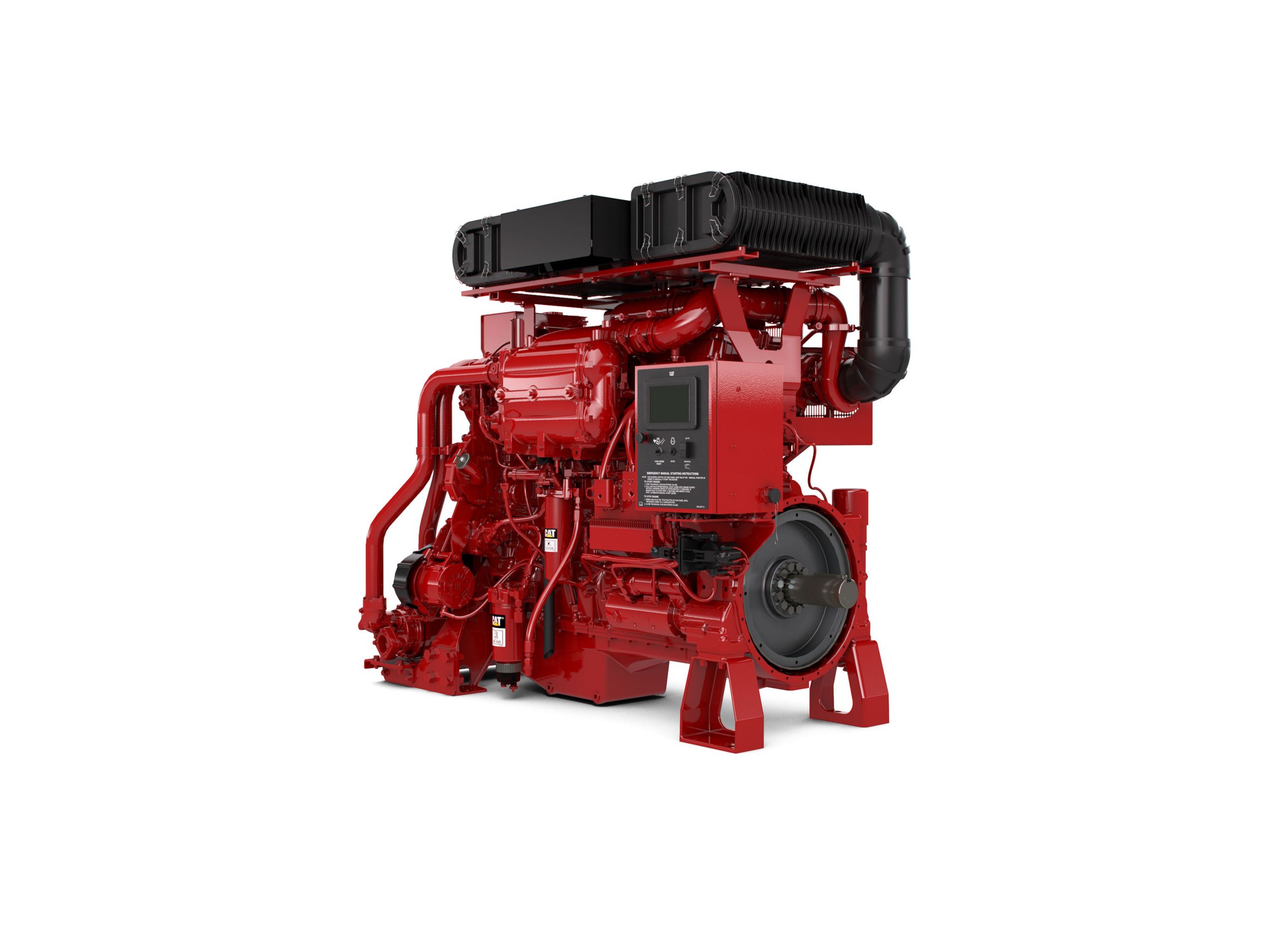
Digital Display mounted in Junction Box, LH side of engine. Displays: Oil pressure, Fuel pressure, Charging voltage, Coolant temperature, Raw water temperature, and Engine hours
Lube System
Crankcase breather, front valve cover
Oil cooler
Lube oil filter
Front sump oil pan
Oil filler
Oil dipstick
Oil pump
Mounting System
Front and rear support
Power Take-Offs
Flywheel stub shaft
Protection System
Stop-Start System, automatic (compatible with NFPA 20 requirements, able to be energized from either of two battery sources and capable of manual starter actuation)
Starting System
24 volt, LH electric starting motor
Jacket water heater (3 kW, 120-240 volt)
General
Vibration damper and guard
Lifting eyes
Automatic variable timing, electronic
Paint - fire pump red
ALL
Air Inlet System
Dual turbocharger: front and rear inlet 127.mm (5.0 in)
Separate Circuit Aftercooled (SCAC)
Optional Air Cleaner - dual element, installed
Charging System
Charging alternator 24 volt, 50 amp
Control System
Dual Electronic Control Units (ECU), primary and secondary with auto switching capability
Electronic governing, PTO speed control
Cold mode start strategy
Automatic altitude compensation
Power compensation for fuel temperature
Programmable low and high idle and top engine limit
Electronic diagnostics and fault logging
Engine monitoring and protection system (speeds, temperature, pressure)
SAE J1939 broadcast (diagnostic, engine status, and control)
Cooling System
Thermostats and housing, vertical outlet
Jacket water pump, gear driven, centrifugal
Heat exchanger installed
Expansion tank
FM Required Raw Water Cooling Loops: 1.5" iron, horizontal or vertical, 1.5" 316 stainless steel, horizontal or vertical, 2" iron, horizontal or vertical (2100 rated rpm only), or 2" 316 stainless steel, horizontal or vertical (2100 rated rpm only)
Exhaust System
Exhaust manifold, dry
Dual turbo: exhaust elbow, dry 203 mm (8 in)
Flywheels and Flywheel Housing
SAE No. 1 flywheel
SAE No. 1 flywheel housing
SAE standard rotation
Fuel System
Electronic unit injector
Fuel filter, secondary (2 micron)
Fuel transfer pump
Fuel sample valve, mounted on fuel filter base
Primary fuel filter / water separator
Instrumentation
Digital Display mounted in Junction Box, LH side of engine. Displays: Oil pressure, Fuel pressure, Charging voltage, Coolant temperature, Raw water temperature, and Engine hours
Lube System
Crankcase breather, front valve cover
Oil cooler
Lube oil filter
Front sump oil pan
Oil filler
Oil dipstick
Oil pump
Mounting System
Front and rear support
Power Take-Offs
Flywheel stub shaft
Protection System
Stop-Start System, automatic (compatible with NFPA 20 requirements, able to be energized from either of two battery sources and capable of manual starter actuation)
Starting System
24 volt, LH electric starting motor
Jacket water heater (3 kW, 120-240 volt)
General
Vibration damper and guard
Lifting eyes
Automatic variable timing, electronic
Paint - fire pump red

