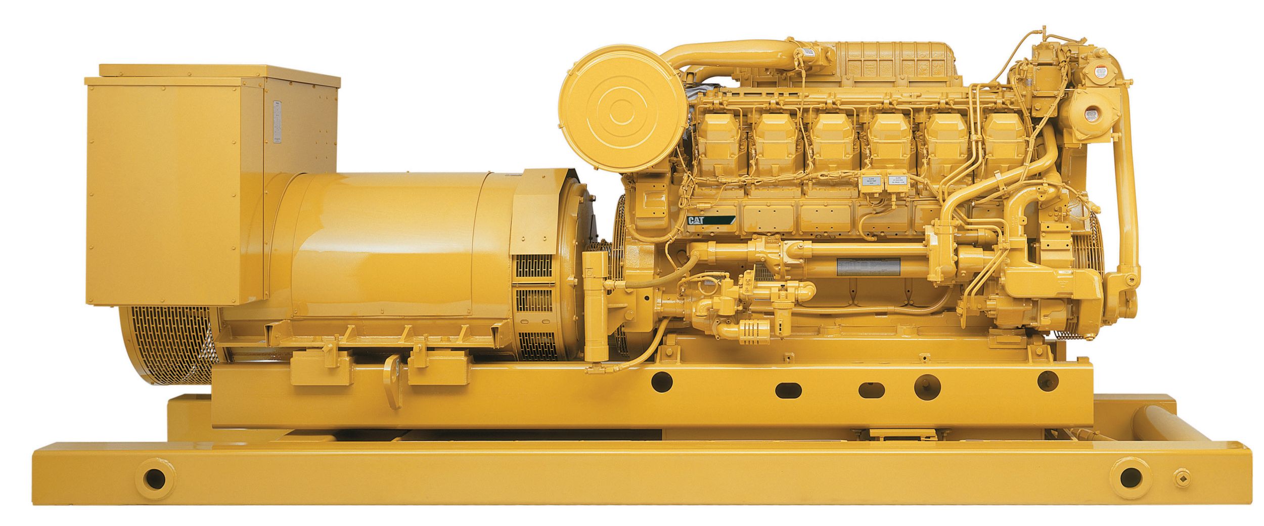
-
Specifications
-
Standard/Optional Equipment
- Catalog
Minimum Rating
1100kV·A
Maximum Rating
1943kV·A
Emissions
IMO Tier I
Weight
33014lb
Stroke
7.5in
Displacement
3175in³
Bore
6.7in
Oil Change Interval
1000h
Engine Control
ADEM A3
Aspiration
Turbocharged-Aftercooled
Fuel System
EUI
Height
86.9in
Length
190.6in
Width
78.3in
Cooling System - Engine
106gal (US)
Lube Oil System - Refill
84gal (US)
AIR INLET SYSTEM
Remote Air Inlet Adapters
CHARGING SYSTEM
Battery Chargers
Charging Alternators
CONTROL SYSTEM
Load Sharing module
Local speed throttle control
Direct rack control interface, 0-200 mA DC control
COOLING SYSTEM
Coolant level sensors
Connections
Air separator
EXHAUST SYSTEM
Flexible fittings
Elbows
Flanges
Flange and exhaust expanders
Mufflers
FUEL SYSTEM
Fuel Cooler
Primary fuel filter
Fuel filters
Duplex fuel filters
Fuel level switch
GENERATOR ATTACHMENTS
Air filter — generator
Bearing temperature detectors
Cable access box
Manual voltage control
INSTRUMENTATION
PL1000T Communication Module
PL1000E Communication Module
Customer Interface Box
Remote panel display
Remote cylinder temperature display
Exhaust temperature thermocouples
Discrete I/O module
Intake manifold temperature sensors
Oil temperature sensor
LUBE SYSTEM
Duplex oil filter
Bypass centrifugal oil filter
500-hour oil pan
Emergency lube oil connections
Oil level regulator
Prelube
Sump pump
MOUNTING SYSTEM
Vibration isolators
POWER TAKE-OFFS
Auxiliary drive shafts and pulleys
STARTING SYSTEM
Air or electric starting motor
Redundant start with select switch
PROTECTION SYSTEM
Spray shielding
Crankcase explosion relief valve
Metal particle detector
GENERAL
Jacket water heater
AIR INLET SYSTEM
Separate Circuit aftercooler core, corrosion resistant coated(air side)Air cleaner, regular dutyDual Turbochargers, 152 mm (6 in) OD straight connection
CONTROL SYSTEM
Caterpillar A-III Electronic Engine Control, LHwith Electronic Unit Injector Fuel SystemRigid Wiring Harness(10 amp DC power required to drive Electronic Engine Control Module)
COOLING SYSTEM
Outlet controlled thermostat and housing, full opentemperature 92°C (198°F)
Jacket water pump, gear driven
Single water outlet connection, includes flange:143 mm (5.6")
Aftercooler fresh water cooling pump (SCAC), gear drivencentrifugal
SCAC pump circuit contains a thermostat to keep theaftercooler coolant from falling below 30°C (85°F)
EXHAUST SYSTEM
Dry gas tight exhaust manifolds with heat shieldsDual Turbochargers with watercooled bearings and heat shieldsExhaust outlet, vertical, 203 mm (8 in) round flanged outlet
FLYWHEELS & FLYWHEEL HOUSINGS
Flywheel, SAE No. 00, 183 teethFlywheel housing, SAE No. 00
FUEL SYSTEM
Fuel filter
Fuel transfer pump
Electronically Controlled Unit Injectors
Fuel priming pump, LH
Rigid fuel return line with customer connection point asbase of engine
INSTRUMENTATION
Overspeed shutdown notification light, Emergency stop notification light
Graphical Unit (Marine Power Display) for analog or digital displayof:
LUBE SYSTEM
Crankcase breather, top mounted
Oil cooler
Oil filter and dipstick, LH
Oil pump, gear-type
Oil pan drain valve, 2" NPT female connection
PROTECTION SYSTEM
A-III Electronic Monitoring System provides customer programmableengine de-ration strategies to protect against adverse operatingconditions
Emergency stop push button (located in Electronic Instrument Panel)Safety shutoff protection:
STARTING SYSTEM
Air starting motor, RH, 620 to 1034 kPa (90 to 150 psi),LH control
Air silencer
GENERAL
Paint, Caterpillar yellow, with black rails
Vibration damper and guard
Lifting eyes
Engine and generator, three-point mounted to sub-base
Lift provisions on base
Oil drain extension
Engine length drip pan
ALL
AIR INLET SYSTEM
Separate Circuit aftercooler core, corrosion resistant coated(air side)Air cleaner, regular dutyDual Turbochargers, 152 mm (6 in) OD straight connection
CONTROL SYSTEM
Caterpillar A-III Electronic Engine Control, LHwith Electronic Unit Injector Fuel SystemRigid Wiring Harness(10 amp DC power required to drive Electronic Engine Control Module)
COOLING SYSTEM
Outlet controlled thermostat and housing, full opentemperature 92°C (198°F)
Jacket water pump, gear driven
Single water outlet connection, includes flange:143 mm (5.6")
Aftercooler fresh water cooling pump (SCAC), gear drivencentrifugal
SCAC pump circuit contains a thermostat to keep theaftercooler coolant from falling below 30°C (85°F)
EXHAUST SYSTEM
Dry gas tight exhaust manifolds with heat shieldsDual Turbochargers with watercooled bearings and heat shieldsExhaust outlet, vertical, 203 mm (8 in) round flanged outlet
FLYWHEELS & FLYWHEEL HOUSINGS
Flywheel, SAE No. 00, 183 teethFlywheel housing, SAE No. 00
FUEL SYSTEM
Fuel filter
Fuel transfer pump
Electronically Controlled Unit Injectors
Fuel priming pump, LH
Rigid fuel return line with customer connection point asbase of engine
INSTRUMENTATION
Overspeed shutdown notification light, Emergency stop notification light
Graphical Unit (Marine Power Display) for analog or digital displayof:
LUBE SYSTEM
Crankcase breather, top mounted
Oil cooler
Oil filter and dipstick, LH
Oil pump, gear-type
Oil pan drain valve, 2" NPT female connection
PROTECTION SYSTEM
A-III Electronic Monitoring System provides customer programmableengine de-ration strategies to protect against adverse operatingconditions
Emergency stop push button (located in Electronic Instrument Panel)Safety shutoff protection:
STARTING SYSTEM
Air starting motor, RH, 620 to 1034 kPa (90 to 150 psi),LH control
Air silencer
GENERAL
Paint, Caterpillar yellow, with black rails
Vibration damper and guard
Lifting eyes
Engine and generator, three-point mounted to sub-base
Lift provisions on base
Oil drain extension
Engine length drip pan
Optional Equipment
AIR INLET SYSTEM
Remote Air Inlet Adapters
CHARGING SYSTEM
Battery Chargers
Charging Alternators
CONTROL SYSTEM
Load Sharing module
Local speed throttle control
Direct rack control interface, 0-200 mA DC control
COOLING SYSTEM
Coolant level sensors
Connections
Air separator
EXHAUST SYSTEM
Flexible fittings
Elbows
Flanges
Flange and exhaust expanders
Mufflers
FUEL SYSTEM
Fuel Cooler
Primary fuel filter
Fuel filters
Duplex fuel filters
Fuel level switch
GENERATOR ATTACHMENTS
Air filter — generator
Bearing temperature detectors
Cable access box
Manual voltage control
INSTRUMENTATION
PL1000T Communication Module
PL1000E Communication Module
Customer Interface Box
Remote panel display
Remote cylinder temperature display
Exhaust temperature thermocouples
Discrete I/O module
Intake manifold temperature sensors
Oil temperature sensor
LUBE SYSTEM
Duplex oil filter
Bypass centrifugal oil filter
500-hour oil pan
Emergency lube oil connections
Oil level regulator
Prelube
Sump pump
MOUNTING SYSTEM
Vibration isolators
POWER TAKE-OFFS
Auxiliary drive shafts and pulleys
STARTING SYSTEM
Air or electric starting motor
Redundant start with select switch
PROTECTION SYSTEM
Spray shielding
Crankcase explosion relief valve
Metal particle detector
GENERAL
Jacket water heater

