-
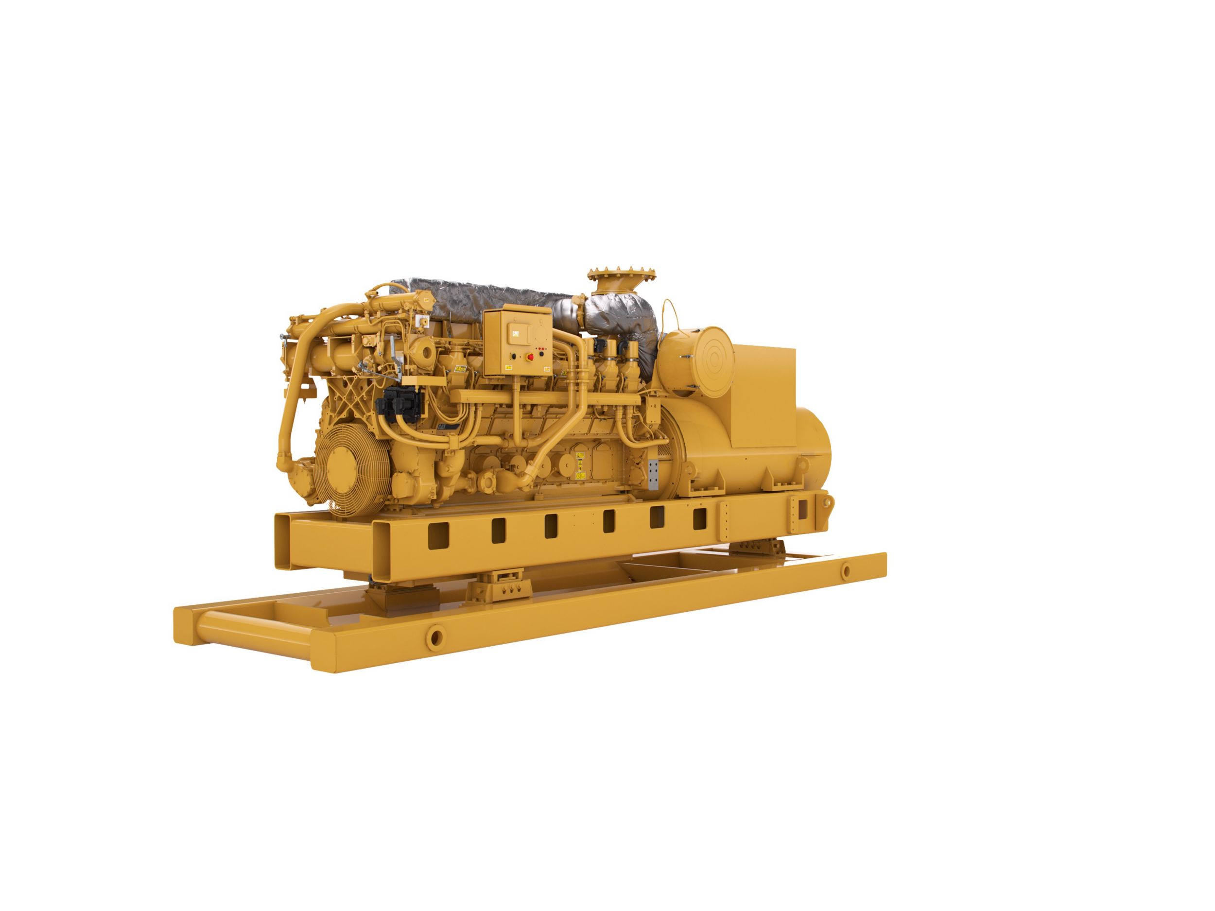
Specifications
-
Standard/Optional Equipment
- Catalog
Minimum Rating
2625kV·A
Maximum Rating
2625kV·A
Emissions
EPA Tier 2, IMO Tier II
Engine Control
ADEM A4
Bore
6.7in
Weight
38581lb
Displacement
4764in³
Fuel System
EUI
Stroke
8.5in
Aspiration
Dual Turbocharged-Aftercooled
Length
264in
Height
99.8in
Width
78.2in
Lube Oil System - Refill
107gal (US)
Cooling System - Engine
62gal (US)
AIR INLET SYSTEM
Aftercooler core, corrosion resistant (air side)
Air cleaner, regular duty with service indicators
Dual turbochargers, rear mounted
CONTROL SYSTEM
Dual Caterpillar A4 electronic engine control with electronic unit injector fuel system and rigid wiring harness.
24 VDC (less than 10A) to be provided by customer at Power Distribution Panel to power engine electrical system.
COOLING SYSTEM
Jacket water (JW) engine cooling and two-stage jacket water/separate circuit (SCAC) charge air cooling
To ensure compliance in use, radiators or heat exchangers must be capable of rejecting sufficient heat to allow proper engine operation at worst site conditions.
The radiator or heat exchanger must supply 48C (118 F)
SCAC cooling water to the aftercooler inlet of at least 200 gal/min at ambient temperature of 30C and at site conditions (including altitude considerations)
EXHAUST SYSTEM
Dry gas-tight exhaust manifolds with heat shields, dual turbochargers with water-cooled bearings and heat shields.
Exhaust outlet: 305 mm (12 in) round flanged outlet, vertical orientation
FLYWHEELS & FLYWHEEL HOUSINGS
Flywheel, SAE No. 00, 183 teeth Flywheel housing, SAE No. 00
Flywheel housing, SAE No. 00
SAE standard rotation
FUEL SYSTEM
Duplex Fuel filter, LH service. Simplex fuel filter, RH service
Fuel transfer pump
Fuel priming pump, RH
Electronically Controlled Unit Injectors
Customer connection located at lower right front of engine
SOLAS shielding
INSTRUMENTATION
Engine mounted instrument panel with four position switch, over speed shutdown notification light, emergency stop notification light, graphical display unit for analog or digital display of: oil and fuel pressure, oil and fuel filter differential, system DC voltage, exhaust and water temperature, air inlet restriction, service meter, engine speed, fuel consumption (total and instantaneous)
LUBE SYSTEM
Top mounted crankcase breather, RH oil filter, RH oil filler, gear type oil pump, deep sump oil pan, recommended use of Caterpillar Diesel Engine Oil 10W30 or 15W40
MOUNTING SYSTEM
Mounting rails and isolation system based on customer request
ELECTRICAL SYSTEM
MCS certified Class I / Divison 2
Low Smoke Zero Halogen Wiring Harness
PROTECTION SYSTEM
A-III Electronic Monitoring System provides customer programmable engine de-ration strategies to protect against adverse operating conditions
Emergency stop push button (located in Electronic Instrument Panel) Safety shutoff protection for oil pressure and water temperature, over speed protection
HAZARDOUS LOCATION
Only electrical system is hazardous environment certified
NEC 500 Class I Division 2 for gas groups C and D
Temperature class is T3 for ambient temperatures from -10 C to 50 C
Class I/ Division 2 CMPD
GENERATOR AND GENERATOR ATTACHMENTS
Class I / Division 2 designed to customer's specifications
Insulation for harsh environment protection
ALL
AIR INLET SYSTEM
Aftercooler core, corrosion resistant (air side)
Air cleaner, regular duty with service indicators
Dual turbochargers, rear mounted
CONTROL SYSTEM
Dual Caterpillar A4 electronic engine control with electronic unit injector fuel system and rigid wiring harness.
24 VDC (less than 10A) to be provided by customer at Power Distribution Panel to power engine electrical system.
COOLING SYSTEM
Jacket water (JW) engine cooling and two-stage jacket water/separate circuit (SCAC) charge air cooling
To ensure compliance in use, radiators or heat exchangers must be capable of rejecting sufficient heat to allow proper engine operation at worst site conditions.
The radiator or heat exchanger must supply 48C (118 F)
SCAC cooling water to the aftercooler inlet of at least 200 gal/min at ambient temperature of 30C and at site conditions (including altitude considerations)
EXHAUST SYSTEM
Dry gas-tight exhaust manifolds with heat shields, dual turbochargers with water-cooled bearings and heat shields.
Exhaust outlet: 305 mm (12 in) round flanged outlet, vertical orientation
FLYWHEELS & FLYWHEEL HOUSINGS
Flywheel, SAE No. 00, 183 teeth Flywheel housing, SAE No. 00
Flywheel housing, SAE No. 00
SAE standard rotation
FUEL SYSTEM
Duplex Fuel filter, LH service. Simplex fuel filter, RH service
Fuel transfer pump
Fuel priming pump, RH
Electronically Controlled Unit Injectors
Customer connection located at lower right front of engine
SOLAS shielding
INSTRUMENTATION
Engine mounted instrument panel with four position switch, over speed shutdown notification light, emergency stop notification light, graphical display unit for analog or digital display of: oil and fuel pressure, oil and fuel filter differential, system DC voltage, exhaust and water temperature, air inlet restriction, service meter, engine speed, fuel consumption (total and instantaneous)
LUBE SYSTEM
Top mounted crankcase breather, RH oil filter, RH oil filler, gear type oil pump, deep sump oil pan, recommended use of Caterpillar Diesel Engine Oil 10W30 or 15W40
MOUNTING SYSTEM
Mounting rails and isolation system based on customer request
ELECTRICAL SYSTEM
MCS certified Class I / Divison 2
Low Smoke Zero Halogen Wiring Harness
PROTECTION SYSTEM
A-III Electronic Monitoring System provides customer programmable engine de-ration strategies to protect against adverse operating conditions
Emergency stop push button (located in Electronic Instrument Panel) Safety shutoff protection for oil pressure and water temperature, over speed protection
HAZARDOUS LOCATION
Only electrical system is hazardous environment certified
NEC 500 Class I Division 2 for gas groups C and D
Temperature class is T3 for ambient temperatures from -10 C to 50 C
Class I/ Division 2 CMPD
GENERATOR AND GENERATOR ATTACHMENTS
Class I / Division 2 designed to customer's specifications
Insulation for harsh environment protection