-
Specifications
-
Standard/Optional Equipment
- Catalog
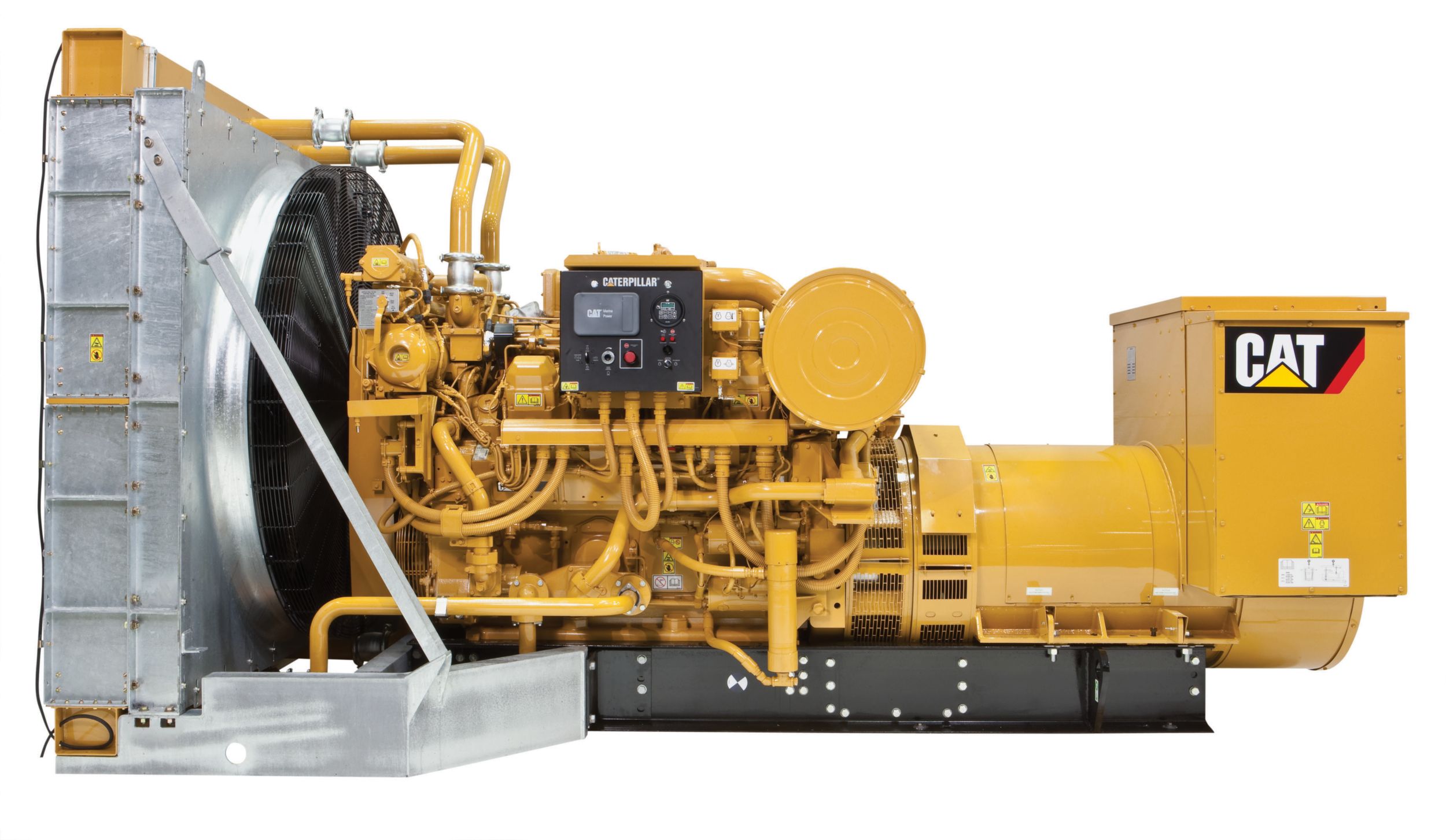
Minimum Rating
799kV·A
Maximum Rating
974kV·A
Emissions
IMO Tier II
EXHAUST SYSTEM
Mufflers — spark arresting
CONTROL SYSTEM
Direct rack control interface
COOLING SYSTEM
Heat exchanger cooling (front engine-mounted includingexpansion tank)
FUEL SYSTEM
Duplex fuel filters
Primary fuel filter
Fuel cooler — titanium plate type
Fuel/water separator
LUBE SYSTEM
Duplex oil filters
Bypass centrifugal oil filters
15° and 25° tilt capability
Air prelube
PROTECTION SYSTEM
Crankcase explosion relief valves
Metal particle detector
INSTRUMENTATION
Pyrometer and cylinder thermocouples
Air cleaner restriction sensors(2),
Intake manifold temperature sensor
Lubricating oil temperature sensor
Fuel filter differential pressure sensors
PL1000
STARTING SYSTEM
Redundant start with selector switch (air-electric, air-air,air-hydraulic, or electric-hydraulic)
GENERAL
Marine Society and IMO certificates
Jacket water heaters
AIR INLET SYSTEM
Aftercooler core — corrosion resistant coating
Air cleaners — dual element, installed
Air inlet shutoff
CONTROL SYSTEM
Caterpillar A-III electronic engine control
Rigid wiring harness (MCS)
COOLING SYSTEM
Outlet controlled thermostat and housing
Jacket water pump — gear-driven, flanged single outlet
Aftercooler fresh water cooling pump — gear-drivencentrifugal
SCAC pump circuit with thermostat
Single water outlet connection
EXHAUST SYSTEM
Dry gas-tight exhaust manifolds with heat shields, dualturbochargers with water-cooled bearings and heat shields
Flexible exhaust fitting/weldable exhaust flange
FLYWHEELS & FLYWHEEL HOUSINGS
Flywheel, SAE No. 00
183 teeth
Flywheel housing, SAE No. 00
MCS approved coupling and generator hub
FUEL SYSTEM
Fuel filter — LH
Fuel transfer and priming pumps
Electronically Controlled Unit Injectors
Flexible fuel lines
Hard fuel return line for MCS requirements
INSTRUMENTATION
Graphic unit (Marine Power Display), LH for analogor digital display of: engine oil and fuel pressure,engine water temperature, system DC voltage, airinlet restriction, RH & LH exhaust temperature, oil andfuel filter differential, service meter, engine speed,instantaneous fuel consumption, total fuel consumed
Operator programmable display, monitoring, alarms andshutdowns
LUBE SYSTEM
Crankcase breather — top mounted
Deep sump oil pan — 1000 hour
Lube oil
Oil drain and valve
Oil filler and dipstick
Oil filter — cartridge-type, LH
Oil pump — gear-type
MOUNTING SYSTEM
Engine and generator three-point mounted into outer base
Oil drain extension
Oil drip pan
PROTECTION SYSTEM
A-III Electronic Monitoring System provides customer programmableengine de-ration strategies to protect against adverse operatingconditions
Emergency stop push button (located in Electronic Instrument Panel)Safety shutoff protection for oil pressure and water temperature, overspeed protection
STARTING SYSTEM
Air starting motor — RH
Electric start control
Air silencer
GENERAL
Vibration damper and guard
Lifting eyes
Paint, Cat yellow
ALL
AIR INLET SYSTEM
Aftercooler core — corrosion resistant coating
Air cleaners — dual element, installed
Air inlet shutoff
CONTROL SYSTEM
Caterpillar A-III electronic engine control
Rigid wiring harness (MCS)
COOLING SYSTEM
Outlet controlled thermostat and housing
Jacket water pump — gear-driven, flanged single outlet
Aftercooler fresh water cooling pump — gear-drivencentrifugal
SCAC pump circuit with thermostat
Single water outlet connection
EXHAUST SYSTEM
Dry gas-tight exhaust manifolds with heat shields, dualturbochargers with water-cooled bearings and heat shields
Flexible exhaust fitting/weldable exhaust flange
FLYWHEELS & FLYWHEEL HOUSINGS
Flywheel, SAE No. 00
183 teeth
Flywheel housing, SAE No. 00
MCS approved coupling and generator hub
FUEL SYSTEM
Fuel filter — LH
Fuel transfer and priming pumps
Electronically Controlled Unit Injectors
Flexible fuel lines
Hard fuel return line for MCS requirements
INSTRUMENTATION
Graphic unit (Marine Power Display), LH for analogor digital display of: engine oil and fuel pressure,engine water temperature, system DC voltage, airinlet restriction, RH & LH exhaust temperature, oil andfuel filter differential, service meter, engine speed,instantaneous fuel consumption, total fuel consumed
Operator programmable display, monitoring, alarms andshutdowns
LUBE SYSTEM
Crankcase breather — top mounted
Deep sump oil pan — 1000 hour
Lube oil
Oil drain and valve
Oil filler and dipstick
Oil filter — cartridge-type, LH
Oil pump — gear-type
MOUNTING SYSTEM
Engine and generator three-point mounted into outer base
Oil drain extension
Oil drip pan
PROTECTION SYSTEM
A-III Electronic Monitoring System provides customer programmableengine de-ration strategies to protect against adverse operatingconditions
Emergency stop push button (located in Electronic Instrument Panel)Safety shutoff protection for oil pressure and water temperature, overspeed protection
STARTING SYSTEM
Air starting motor — RH
Electric start control
Air silencer
GENERAL
Vibration damper and guard
Lifting eyes
Paint, Cat yellow
Optional Equipment
EXHAUST SYSTEM
Mufflers — spark arresting
CONTROL SYSTEM
Direct rack control interface
COOLING SYSTEM
Heat exchanger cooling (front engine-mounted includingexpansion tank)
FUEL SYSTEM
Duplex fuel filters
Primary fuel filter
Fuel cooler — titanium plate type
Fuel/water separator
LUBE SYSTEM
Duplex oil filters
Bypass centrifugal oil filters
15° and 25° tilt capability
Air prelube
PROTECTION SYSTEM
Crankcase explosion relief valves
Metal particle detector
INSTRUMENTATION
Pyrometer and cylinder thermocouples
Air cleaner restriction sensors(2),
Intake manifold temperature sensor
Lubricating oil temperature sensor
Fuel filter differential pressure sensors
PL1000
STARTING SYSTEM
Redundant start with selector switch (air-electric, air-air,air-hydraulic, or electric-hydraulic)
GENERAL
Marine Society and IMO certificates
Jacket water heaters